
Although LiFePO4 batteries are quite forgiving in most normal operating conditions, they are very sensitive to overcharging and over-discharging. Even one single mistreatment can damage the cells permanently, reducing capacity significantly or even destroying them.
In order to prevent damage to the cells, a protective device is needed that permanently monitors the cells and takes action if dangerous operating conditions are detected.
Possible actions range from alarms to shutting off charging sources or loads, or even shutting down the complete system.
There are many commercially available options on the market. After some research we settled on the HousePower BMS from CleanPowerAuto LLC.
This BMS is a very basic one, it does one job, and without any configuration.
It is also quite cheap, compared with other solutions.
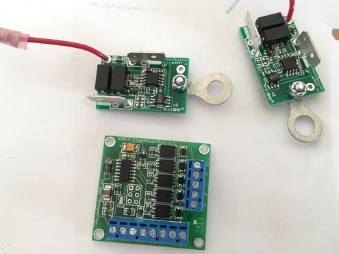
The complete HousePower BMS system consists of the BMS itself which comes in a square PCB with terminal blocks.
In addition you need one cell module for each cell to monitor (4 in our case).
The Box
While mounting the cells module themselves on the LiFePO4 cells is acceptable (the top of the cells is typically a quite protected area), the BMS PCB is not something one would like to mount anywhere directly in a marine application.
It needs a protective housing, and I also wanted something that can be easily swapped in case of a problem. I planned to build at least one spare (we'll get to that later).
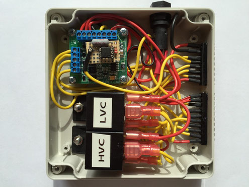
On the image to the right you can see the final box. It exports all the electrical connections of the BMS module via two pluggable connectors (Riacon 3.81 mm).
I also added two relays in the box which take the HVC (High Voltage Cutoff) and LVC (Low Voltage Cutoff) signals and convert them to potential free outputs.
These relay outputs also provide the HVC/LVC events inverted in case I need them.
Status LED
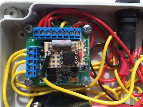
The BMS module PCB contains a SMD LED that indicates the BMS status. In normal operation it flashes once per second but may indicate problems (HVC, LVC) with different light patterns.
Unfortunately the BMS status signal (LED) is not exported on the BMS terminals, but I was able to extract the information using an opto coupler and two resistors (see schematics).
This allows me to drive a LED on the boat's main panel showing the BMS status.
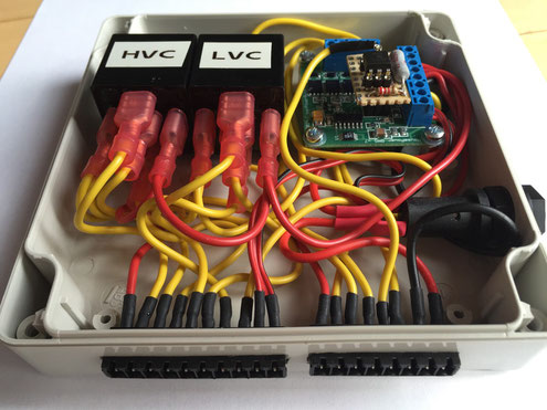
This is a side view of the box, you can see the Riacon connectors which I glued in the box using epoxy.
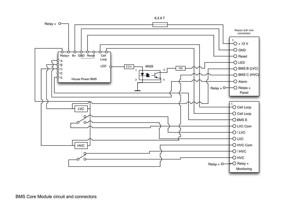
Below you can see the full schematics of the module, it is later used as a "standard" module in the higher level schematics of the boat.
Schematics
Pin Assignments
Riacon 8 pin connector
Pin 1: + 12 V
Pin 2: GND
Pin 3: Reset (pull to ground to reset)
Pin 4: LED (connect LED to +12 V using a current limiting resistor, the internal circuitry contains a 150 Ohm 2 W resistor to avoid damage to the opto coupler in case of a short to + 12 V)
Pin 5: BMS B output (LVC, output is pulled to ground when active)
Pin 6: BMS C output (HVC, output is pulled to ground when active)
Pin 7: BMS Alarm output (output is pulled to ground when active)
Pin 8: Relais + (carries + 12 V if BMS is active, internally fused with 6,3 A)
Riacon 10 pin connector
Pin 1: BMS Cell Loop (connect to cell module chain)
Pin 2: BMS Cell Loop (connect to cell module chain)
Pin 3: BMS E output (main contactor, output is pulled to ground when active)
Pin 4: LVC Com (internal LVC relay, common contact)
Pin 5: !LVC (internal LVC relay, normally closed contact)
Pin 6: LVC (internal LVC relay, normally open contact)
Pin 7: HVC Com (internal HVC relay, common contact)
Pin 8: !HVC (internal HVC relay, normally closed contact)
Pin 9: HVC (internal HVC relay, normally open contact)
Pin 10: Relais + (carries + 12 V, internally fused with 6,3 A if BMS is active)
Previous article:
Write a comment
garry crothers (Wednesday, 05 October 2016 09:51)
I'm still building my battery/charging system, abd find your artucle very helpful, many thanks for publishing your hard work.
I am trying to understand the relay expansion circuitry.
can you confirm or otherwise that pins 8 and 10 on the 2 connectors are linked internally via 6.3A fuses to pin 1, the 12v BMS input line.
thanks
garry
Martin Bartosch (Wednesday, 05 October 2016 09:57)
Yes, this is correct. The House Power BMS board has an internal, direct connection between the B+ and Relay+ connectors.
This means that the 8 and 10 of the connectors effectively are +12 V fused with the 6.3 A fuse in the above circuit.
The important thing is that the HP BMS board pulls its A-E outputs to ground to activate the relay.
This means that instead of using Pin 8 and 10 for wiring the external relays/contactors you can also use any properly fused +12V connection.
Matt Gross (Wednesday, 10 April 2019 16:37)
Thank you for this! I have a mini BMS with a single protector contactor but looking for a way to integrate the HVC and LVC with relays. This is exactly how I pictured doing it, it's just nice to see someone else did the same thing. Thanks!
Peter (Wednesday, 17 March 2021 18:51)
Hello, I need a miniBMS Balancer. Because I have destroyed mine. Where can I buy a new one or do I have to replace the whole BMS? Many thanks for your opinion.
Martin Bartosch (Thursday, 18 March 2021 08:07)
The House Power BMS is no longer available (and I am not affiliated with the producer, I just bought and used their product).
I think the only option is to repair the damage (if possible), try to find a used one or replace the entire BMS with a different one.