
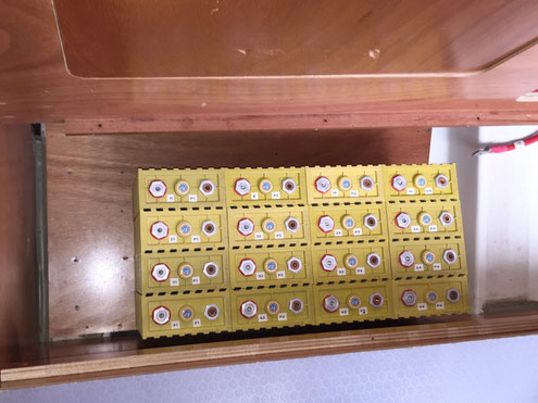
The 16 individual Winston 100 Ah cells will have to be arranged and fixed in the form of a battery block in order to prevent unwanted movement during passage or worse in case of capsizing.
This image was taken during a dry run for checking the available space in the battery compartment before the necessary parts were ordered.
Requirements:
- physically constrain movement of the cells, prevent battery pack from unwanted movement in rough seas, and also prevent block from falling apart if capsizing should happen
- compress cells (or at least prevent physical expansion) in case of excessive charge or discharge (if the cells are prevented from bulging capacity loss due to electrical mistreatment can be reduced)
- electrically connect the cells, taking into account the maximum expected current through the battery.
The concept for fixing the cells makes use of perforated stainless steel brackets, in the style of bookends on a cupboard. We ordered them custom-built from Maschinenbau Feld GmbH. The lower part of the steel brackets are to be bolted down on the wooden floor, the parallel sides will be pulled together tightly with six 5 mm threaded rods.
In a situation where the cells are really bulging I would expect an internal pressure of 100 - 200 kPa (100 - 200 kN/cm²) before the emergency pressure vents open. When using 3 mm slotted stainless steel plates and 6 threaded rods, screws and bolts tightened with about 5 Nm, resulting in an estimated normal force of about 3 - 5 kN pressing against the cells.
My nephew Julius is studying mechanical engineering, and I asked him for an opinion on the mounting option I planned. I gave him some parameters of the battery pack and my idea of the perforated metal plate and asked if he could give me an estimate on the expected bulging in an extreme situation. He actually simulated this (!) and gave me the rendered results. Thanks again for this great help!
Julius computed the maximum bulging in the middle of the pack would be around 20 mm - which is quite a lot, but I accepted it for my case as I don't expect it to happen at all.
In order to connect the cells electrically, we got in touch with the German company Kabelvertrieb Hesselmann GmbH, and after describing what we needed they custom-built braided and tinned copper ground straps (36 of them, each sized 35 mm²) for our purpose. The straps were even directly sent to our boat in Spain.
Finally, an acrylic cover for the battery was custom built by H&S Kunststofftechnik to prevent the top of the bank from accidental shorts or physical damage due from falling items.
All these custom build tasks were prime examples of the excellent service with the smaller companies we dealt with during the preparation of our boat!
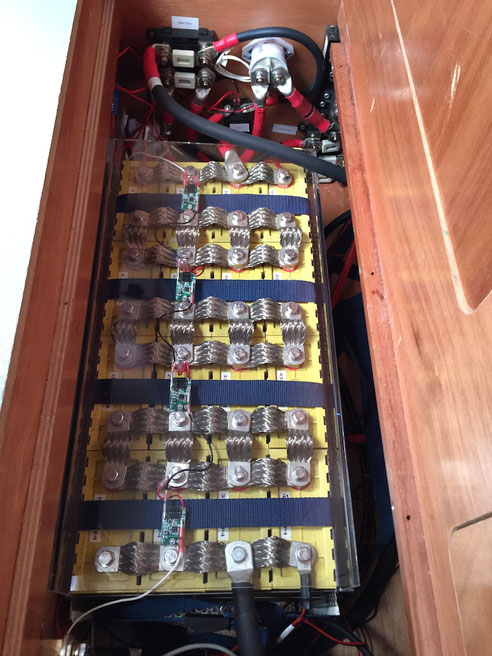
This image shows the final installation of the battery block.
If you look closely on the bottom part of the picture you can see the slotted steel plates attached to the wooden base and the threaded steel rods tightening the battery block. The blue belts run around the entire block and fix the 4P cell packages.
On top of the 4P cell packages you can see the HousePower BMS cell modules which monitor cell voltage.
In order to prevent accidental contact of metal items with the cell connectors (or wearing the isolation of the thick cable on top of the block), a acrylic cover lid was built which fits on top of the block like a bracket.
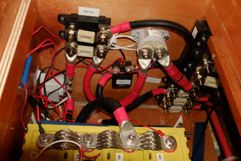
On the left lower side of this image the main contactor can be seen, the LVC contactor is on the right and the HVC relay is just below it.
The main distribution is implemented using Philippi SHD-1 fuse holders which are connected with SDV bars.
The image does not show the final state, or course: the wiring of the smaller wires is still subject to a substantial clean-up.
Main fuse is dimensioned for 355 A, the cable size for the main connections is 120 mm².
Write a comment
CORY (Sunday, 25 June 2017 02:46)
Do you have parallel packs connected in series across every cell? Is that how the 4p4s is supposed to be configured?
Thanks
Cory (Sunday, 25 June 2017 02:49)
Also looks like your main pos and neg cables a coming inot the middle. Why not opposite ends across the battery array? Are u doing cell monitoring or are you expecting the parallel packs to stay balanced on their own from (ie only need to monitor one cell per pack due to parralel connections)?
Cory (Sunday, 25 June 2017 16:57)
Thought I posted this but I guess it didn't :/
Do you really need in the 4p4s configuration to have every cell between packs wired in serial across the packs?
Your pos and neg feeds are coming into the middle of the end packs vs opposite corners?
Looks like you only have one monitor per parrallel pack. Is that because you are counting on the parallel connection to keep the cells within the pack balanced?
Thanks for any response.
Martin Bartosch (Sunday, 25 June 2017 18:18)
Hi Cory,
You did post, but we have enabled moderation on the comments of these Blog, as we keep getting link spam if we don't moderate.
The wiring is pretty standard. First arrange 4 cells in parallel. Then wire the 4 resulting parallel packs in serial configuration.
The plus and minus cables are not attached to the middle because this is difficult to do with 4 posts. I am aware that this is not symmetric and will likely result in a slight internal imbalance in the outer cells, but I am willing to take that "risk".
Someone has suggested to wire the main connects "diagonally" (seen over the whole pack). This might be sensible, but for me it's not worth the effort to rewire.
Yes, I am using 4 connectors instead of 1 for the serial connection of the 4P packs. The reason is that each braided strap only has 35 mm^2. This is not sufficient for the designated maximum current of the pack, hence I am using 4 of them, resulting in 140 mm^2 total for the serial connection between 4P packs.
It is impossible to monitor individual cell voltage of a parallel pack, hence only one cell module for each 4P pack.
HTH
Martin
Serge (Saturday, 30 May 2020 17:02)
Hi Martin. great post and beautifully done job on engineering. I wonder how the battery has performed for you? Also, why you decided not to wire 4S4P config and instead went with 4P4S? My understanding that you would be able to balance every cell that way, however, not balancing every cell might be a non-issue in the first place?
I am planning a similar setup for 24V system on my boat and I wanted to do a 400 Ah battery using Winston either 400 Ah or 200 Ah cells. Any work of wisdom would be appreciated. Thank you! Safe sailing.
Serge
Martin Bartosch (Sunday, 31 May 2020 00:16)
Hi Serge, thanks for your feedback. Always nice to hear that these posts help other people. The system works great so far, a LiFePO4 bank really is a great improvement for long term cruising.
Regarding the cell topology:
If you set up a 4S4P topology, you essentially create four separate battery packs which are paralleled together. The benefit is higher resilience with regard to failures (if a string fails, there are 3 strings left), but the cost and complexity is higher, as one needs 4 BMS and 4 * 4 = 16 cell monitors.
By arranging the cells in a 4P4S pack you essentially get only 4 big cells to monitor. Assuming zero resistance the paralleled cells will have identical potential and, at least theoretically, identical SoC.
However, today I would prefer to have less paralleled cells, ideally 2P4S or even 1P4S. Less wiring, fewer losses, fewer chances for failures. In our case, the physical dimensions of the cells more or less demanded choosing the 100 Ah cells.
If it had been possible, I'd probably have chosen the 200 Ah cells or even the 400 Ah cells.
Cheers
Martin
Guilherme Martins (Friday, 26 June 2020 20:15)
Hi,
I am in the process of designing my build at the moment.
Learned a crazy amount of stuff from this post, a huge thank you for sharing this!!!!
Stay safe.
All the best
Martin Bartosch (Saturday, 27 June 2020 19:03)
Thanks for the feedback, Guilherme! Glad this series helped you designing your solution.
Cheers
Martin
Jemma (Monday, 28 November 2022 07:44)
Can I share your blog on my Linkedin page?
I am Winston manufacturer. You wrote very well and detailed.
If you don't mind, I'd like to hear more feedback from you to improve our products.
Martin Bartosch (Monday, 28 November 2022 09:22)
Hi Jemma, nice to see that Winston noticed this blog. Of course you can link this blog from social media or the Winston web page!
So far we are very happy with the Winston cells - very solid build quality, and performance is as new even 6 years after installation.
Cheers
Martin