
2016-06-30 Update: As Jim pointed out in the comments - and which was meanwhile confirmed by Balmar support - the Digital Duo is not a DC/DC charger, it is rather a switching device which will not step up voltage and hence lead to undercharging the starter battery. This device was replaced by a Sterling Pro Charge B BBW 1212 (more or less a drop-in-replacement).
2019-12-13 Update: Today I would choose the smallest Victron "Orion-Tr Smart DC-DC Charger Isolated" charger. Advantages: much smaller and lighter and most importantly input and output are isolated. This was not the case for the Sterling charger, and I see this as a significant drawback.
We have now defined our requirements and constraints. Based on this information we evaluated the options for charging systems and decided on the solution most suitable for our own needs.
The next step is to select individual marine electrics components with the desired properties and create a system design, taking into account the properties of the components as well as marine electrics safety requirements.
The design should also consider possible failures of each individual component and either provide failsafes, backup solutions or allow easy workarounds for potential problems.
The following design has been developed after reading the entire (!) thread on LiFePO4 batteries thread on the Cruisers Forum, the excellent background and summary article on LiFePO4 batteries by Compass Marine, doing my own extensive research and finally reading dozens of marine electrics manuals and data sheets.
I would like to thank all contributors on the Cruisers Forum, in particular "Maine Sail" for providing useful insight, experience and thoughts!
This article was written to contribute to this amazing community by giving back some useful work myself.
Disclaimer
- Follow ABYC, German Lloyd or similar guidelines when implementing boat electrics, in particular when it comes to cable sizing, fusing and installation.
- If such a system design is not implemented properly in real life you may pose your property, your boat or even your life at risk!
- The design also contains an AC high voltage portion. Do not work on any part of an AC installation unless you have the required expertise yourself. Consult an electrician for this.
- This design describes our own solution as we implemented it on our boat, based on our needs. This is by no means the only way to solve the problem, it is a solution that makes most sense to
us.
Do not copy this design blindly without completely understanding the full implications. - If you consider copying all or part of the design please note that you are doing things at your own risk. Note that we are dealing with potentially very big currents flowing through the cables. Also note that this design is highly customized and unusual. You will likely have to maintain everything yourself, because there might be few marine electricians who will understand what is going on.
- When implementing such a system size cables properly (design for voltage drop and for maximum current)
- All fuses must be calculated to fit cable sizes and component ratings
- Fuse all connections connected to battery positive as close as possible to the battery. Fuses must be sized to protect the wiring behind them.
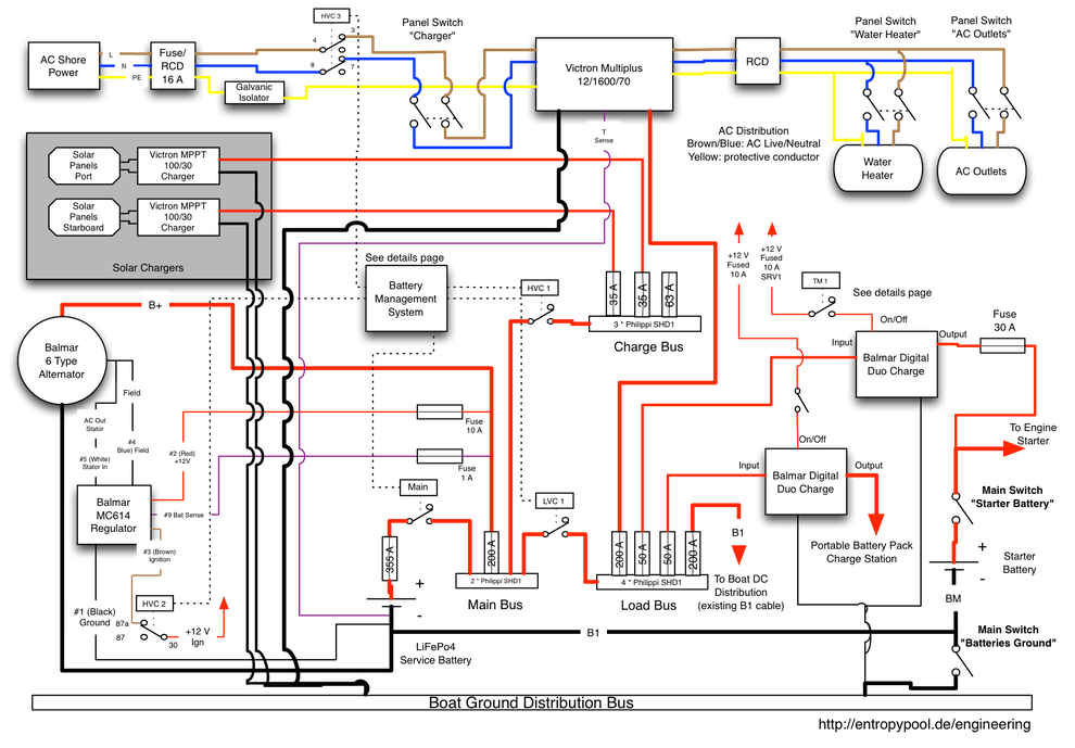
Overall Schematics
Let's start with a view on the final design to give an overview on the complete solution.
The following image shows the overview schematics as it was finally implemented on the boat.
Although it is mostly complete with regard to the most important wiring and connections, some intricacies have been left out and are contained on several more detailed schematics further below on this page. (This is especially true for the LVC/HVC relays and contactors. Some of them need "inverted logic" to function properly, something we need to address explicitly because the House Power BMS does not directly support it. For the sake of understanding the design these details are distracting, so we focus on main function first. Refer to the BMS Wiring Details section for full implementation details.)
Schematics Teardown - The Design Explained
The overall design may not be obvious to everybody and may raise some eyebrows, so we will take it apart and explain the individual components and decisions.
Core System: Battery, BMS, Alternator, Charging Starter Battery
In order to understand the above diagram better, let's rip out some of the less important components and only look at the core components first.
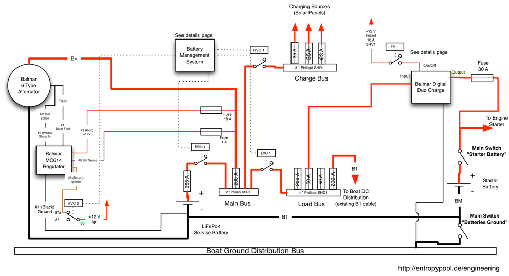
Service Battery
In the center you can see the simplified LiFePO4 service battery. The negative side of the battery pack is connected to the boat distribution via existing cable B1, the old lead acid negative connection.
The "Main Switch - Batteries Ground" already exists and disconnects the existing boat electrics from battery ground.
Main Bus Distribution
The fused positive side of the service battery is switched by the Main Contactor and connected to the Main Bus. The Main Bus forms the main distribution for loads and charge sources.
(The Buses may look a bit strange in the diagrams. The components I chose are Philippi SHD1, fuse holders which can be cascaded and connected with a metal bar to form a bus bar. On the other side you get fused exits, hence the symbol.
The Main Contactor is controlled by the BMS (terminal E of the House Power BMS). It is closed whenever the BMS is switched on and the BMS measures voltages within the protection level thresholds. The Main Contactor should be dimensioned to switch the maximum acceptable current in the system.
The B+ cable coming from the alternator is connected to the main bus, fused to fit the alternator cables and rated current (Note: See below for details on the decision not to connect the alternator B+ directly to the battery but via the Main Contactor).
Charge Bus
The Charge Bus is connected to the Main Bus via contactor/relay HVC 1. This relay should be rated to switch the maximum charging current expected.
HVC 1 is closed whenever the BMS is active and no HVC (High Voltage Cutoff) has occurred.
All charging sources which may safely be "just turned off" are connected to the Charge Bus. In our case this only applies to the solar panels. If we had opted for a fuel cell or a hydro generator they would go here as well.
Note: The alternator is not connected to the charge bus because it is not to safe dump the load on an alternator which is generating power, this would destroy the internal diodes. Instead, the alternator must be shut down safely by cutting its field current. See below for details.
Load Bus
The Load Bus is connected to the Main Bus via contactor LVC 1. This contactor should be rated identical to the Main Contactor.
LVC 1 is closed whenever the BMS is active and no LVC (Low Voltage Cutoff) has occurred.
The existing B1+ cable (previously attached to the positive side of the old lead acid batteries) is connected to the load bus. In addition all other loads go here (see below).
By connecting the B1+ cable to the load bus we essentially attach the complete existing electrics to the load bus. In the existing wiring the old chargers and the old battery combiner have been removed, so B1+ will only act as a load, never as a charging source.
While a HVC event will not influence the loads on the boat distribution a LVC will let the whole boat go dark immediately. Understandably this situation should generally be avoided (in particular when cruising), and ample warning must be given to warn the crew before a LVC is bound to happen.
The BMS will not create such a warning, instead we will program the battery monitor device to track state of charge and pack voltage and generate an alarm if any of these parameters reach critical levels.
Alternator
The old alternator is replaced by a high performance model with external regulation which is performed by a Balmar MC 614 regulator. This is one of the few alternator regulators on the market that can be programmed - which is a requirement for this use case. (Primarily absorption and float voltage levels must be adjusted to LiFePO4 requirements.)
Alternator B- is directly connected to the battery monitor shunt on the negative side of the service battery pack so alternator current is measured by the battery monitor but is not subject to more voltage drop than necessary.
Alternator B+ is connected to the Main Bus. This is a controlled risk, because this means that if the Main Contactor opens while the alternator is still generating power, it will probably blow internal diodes. We have to make sure that in all normal cases this contactor will always be closed.
For me it was very important to be able to completely isolate the positive side of the battery bank - hence this compromise.
The alternator regulator is programmed to deliver 13.8 V absorption voltage and 13.3 V float voltage. The absorption voltage is well inside the safe range of the battery pack and should never lead to overcharging the batteries - the charging current simply tapers off when approaching 100 % state of charge. The HVC is merely a safety measure in the case the regulator fails to deliver the programmed voltage.
In the (unlikely) case of a HVC event relay HVC 2 is activated by the BMS. The normally open contact of this relay then interrupts the connection of the regulator Ignition input (#3) and effectively cuts the field current on the alternator. It will stop charging but the alternator regulator will remain on "on" state.
The voltage sense wire of the MC 614 regulator needs to see battery voltage directly. The regulator uses this sense wire to control its output voltage according to programming. A compromise again: I connected it to the stud where the B+ wire of the alternator is attached. It is close enough to the battery and sees the alternator generated voltage. As discussed, I decided against connecting B+ to battery plus directly, so I had to do the same with voltage sense (reason: I wanted to eliminate conditions where voltage sense does not see generated voltage).
As mentioned an alternative (possibly better, I will have to think about this) is to connect B+ and voltage sense directly to battery plus.
In order to provide tachometer output to the instrument panel the alternator stator output is connected to the MC 614 regulator. It divides the unrectified AC of the alternator to produce a proper tachometer signal which is fed back to the tachometer on the helm station.
An alternator temperature sensor is attached to the alternator case and wired to the regulator, the MC 614 then reduces field output if the alternator starts overheating.
Starter Battery
The starter battery itself and the "Main Switch - Starter Battery" on the right hand side has been left untouched. The boat came with a battery isolator and the old battery chargers, charging both service and starter battery via the battery isolator.
As it is not possible to charge two different battery systems from the same charging sources via a battery isolator without causing damage to one of the batteries over time, the battery isolator was removed from the design.
Charging the starter battery seemed tricky at first. I briefly considered two alternators, each charging one battery, but this would have been waste of material and charging capacity.
After some out-of-the-box thinking I decided to take an unusual approach to charging the starter battery.
DC-DC Charger
In this design the starter battery is charged via a DC-DC charger (a Balmar Digital Duo Charge - replaced by a Sterling Power Pro Charge B BBW 1212). This device accepts input in the normal 12 - 14 V range of a DC distribution and converts it to a voltage suitable for charging a normal lead acid battery (possibly up-stepping voltage a bit).
The input of the Digital Duo BBW 1212 is connected to the load bus of the service bank. The output goes to the positive terminal of the lead acid starter battery via the main switch. The Digital Duo BBW 1212 is working (i. e. charging the starter battery) whenever the following two conditions are true:
- the load bus carries +12 V
- the On/Off wire of the Digital Duo BBW 1212 charge carries +12 V (effectively turning the device on)
This means that in order to keep the starter battery permanently charged, we could simply connect On/Off permanently to +12 V. However, in this case the Digital Duo BBW 1212 is always on and permanently draws power. In order to preserve energy I designed some simple circuitry to limit activity of the Digital Duo BBW 1212 - we'll get back to this later (see the "Starter Battery Charging Details" chapter).
Solar Panels and Inverter/Charger
Now we should have a look at the rest of the installation, this time leaving out the components we already explained:
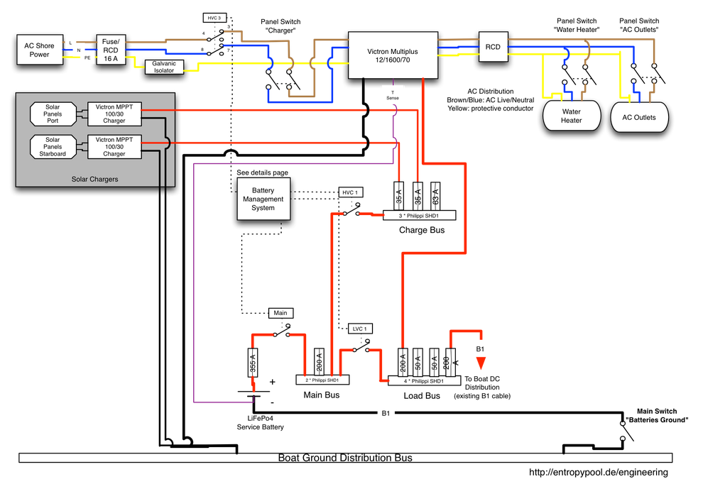
Solar panels and MPPT chargers
Two banks of solar panels, each connected to a MPPT charger are added.
The output of the MPPT chargers are connected to individual fuses on the charge bus. The MPPT chargers are also programmed to 13.8 V absorption voltage and 13.3 V float voltage.
HVC 1 cuts charging if the MPPT devices overcharge the LiFePO4 bank for any reason (should not happen if programmed correctly and working normally).
Shore power charger/inverter
The Victron Multiplus Inverter/Charger is connected to the load bus. It is a special case, because this component can be both a load (running in inverter mode) and a charging source (when connected to AC shore power).
Connecting the Multiplus to the load bus addresses the problem that the inverter could possibly discharge the battery beyond the LVC threshold. In this case the BMS will trip the LVC 1 contactor and prevent further discharging.
When running in charger mode the charge current is flowing from the charger through the load bus into the battery. Obviously this does not work when a LVC has happened but this should be a rare exception.
In order to prevent overcharging, the shore power AC side of the Multiplus is routed through HVC 3, a normally closed AC rated double pole relais (250 V, 16 A rating minimum).
In case of a HVC cutoff, HVC 3 activates and opens the circuit to the Multiplus charger, disconnecting it from shore power.
Just like the other charging sources, the Victron Multiplus is programmed to supply 13.8 V absorption and 13.3 V float.
The Inverter/Charger includes a "T Sense" wire which measures battery temperature on the negative terminal of the battery. It seems like it also doubles as voltage sense for the Multiplus, so even though temperature sensing is not necessary on a LiFePO4 bank, I connected the T Sense to battery minus.
AC Wiring
You definitely need two RCDs in the AC circuitry. One should be located at the shore power side (near its breaker). I chose a combined RCD/breaker on the shore power side.
The other RCD should be directly behind the inverter AC output. The Victron Multiplus already contains a 16 A thermal breaker and limits output current properly so no additional breaker is needed on the AC output side. The RCD is obligatory, though.
BMS Wiring Details (Monitoring and Control)
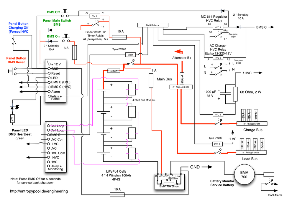
This diagram is basically a "zoomed in" version with BMS related components of the very first overall diagram. I needed this in order to exactly document where to connect which wire to achieve the desired results. In addition, it shows how the relay logic is implemented (some relays must be inverted to function properly). The schematics also contains some interesting tweaks which are worth explaining.
BMS On/Off (service battery main switch)
The easiest way is to simply connect the +12 V input of the BMS (Pin 1 of the BMS upper connector in the diagram) to +12 V via a fuse and a switch.
This switch then becomes the service bank main switch. If "on" the BMS gets power and - provided all voltages are within nominal range - the BMS will activate the main contactor. Switching "off" will immediately shut down the complete system. Switching off the BMS must be avoided in certain situations, primarily when the alternator is charging the LiFePO4 bank. In other words: when using a simple On/Off switch never turn it off while the engine is running.
Optional: BMS On/Off buttons with "soft shutdown feature"
In order to avoid problems with switching off the BMS the hard way via a switch, it is possible to replace the BMS switch with some protecting logic.
This is totally optional but makes switching off the BMS fail-safe at the cost of added complexity. See top left part of above diagram (green text, On/Off buttons and TM 2 relay).
Basic idea: connect BMS +12 V behind the Main Contactor. Once the Main Contactor is on, the BMS gets power and keeps the Main Contactor on (self-latching).
To switch the BMS on, briefly provide +12 V to the BMS via an "On" button (green text in the diagram above). Note, however that if you simply wire this button between BMS + and battery positive, you are essentially bypassing the main contactor. With a very thin wire. Not a good idea!
To avoid this, add two diodes (Schottky low drop, 10 A rated) to avoid "normal load" current bypassing the main contactor. The diodes must be dimensioned to sustain the normal BMS load (basically HVC/LVC coil currents).
Switching the BMS off shall be done via a different button (green text in the diagram above). Pressing the button shall first invoke a HVC-like situation, shutting down the alternator. If the button is pressed for more than 5 seconds, the BMS +12 V connection shall be interrupted. The Main Contactor will then open and the BMS will be without power, isolating the whole system.
If the button is released before the 5 second delay is over, the alternator will resume charging, and BMS/Main Contactor will remain online.
This is achieved by triggering a timer relay (I chose a Finder 39.81.12 and programmed it to AI (delayed on) with a 5 seconds delay). Once the timer relay sees +12 V between A1 and A2 it waits 5 seconds before opening 15-16 (normally closed) and closing 15-18 (normally open). If the Main Bus has power, the BMS gets +12 V via the normally closed TM 2 contacts 15-18.
This means once the timer relay triggers, it shuts down the BMS.
To shut down the alternator, we connect the "Off" button to HVC 2 (alternator regulator shutoff) via a Schottky Diode, temporarily disabling alternator charging as long as the button is pressed. The other diode prevents the rest of the HVC circuitry "seeing" the alternator shutdown.
LVC and HVC relay wiring
The overall schematics diagram at the top of this article was unspecific how the LVC and HVC relays were actually connected. This diagram shows the exact details how to wire them.
When designing the system I was faced with the problem that the House Power BMS is somewhat limited with regard to LVC and HVC output. The BMS module's logic pulls down its LVC/HVC outputs (B and C terminals) when the event occurs, this means they are normally open.
The BMS B and BMS C outputs pull to ground whenever all of the following conditions are true:
- the BMS is switched on
- an LVC or a HVC event has occurred
In my design I needed to activate the LVC 1 and HVC 1 connectors to close the circuit. The BMS outputs had to be inverted!
Partly for this reason I repackaged the BMS in a modular box with defined output connectors. In this box I had added relays for LVC and HVC and routed the relay connections to my module connector. By using the module's outputs I now have the inverted signals (marked !LVC and !HVC - read "not LVC" and "not HVC").
The !LVC and !HVC of my module package (in conjunction with the above wiring of the module) pull to ground whenever all of the following conditions are true:
- the BMS is switched on
- the BMS has detected nominal voltages outside protection levels
- LVC/HVC has not occurred
HVC 2 and HVC 3 use normally closed contacts, so we want them to activate on HVC - hence they are wired to BMS C.
Coil current optimization
Relays need a higher voltage to change state than to hold. Typically a relay will even stay closed when the coil volate is reduced to half (or even less) of its nominal voltage. It is possible to save a lot of energy by reducing coil voltage (or limit coil current) once the relay has activated.
The Tyco EV200 contactors I chose for Main and LVC contactor include a "coil economizer" circuit doing exactly this. The residual current flowing through the EV200 is much less than the current required during the short period of activation.
However, my other relays do not have this optimization. They draw a lot of power and dissipate precious energy.
To reduce power consumption of HVC 1 (a 100 A rated relay without any built in optimization) I added a 68 Ohm resistor and a 1000 µF capacitor in series to the relay coil. The resistor has been dimensioned to form a voltage divider with the relay coil, effectively reducing coil voltage to a bit less than 50 % of the nominal voltage (it is necessary to measure the coil resistance to size the resistor's value properly).
When the relay coil is energized, the capacitor is discharged and draws a lot of current for some fractions of a second. Essentially this shorts the resistor for this time, the full 12 V are on the coil contacts, activating the relay. Once the capacitor is fully charged, current stops flowing through it. The coil current has to flow through the resistor which reduces the voltage on the coil to about 50 % and limits total current flowing through it. The resistor has to dissipate roughly 0.5 W (hence a 2 W resistor). There are more efficient relay coil optimizer circuits, but for now this will do.
The capacitor and the resistor can be left out completely, of course!
Panel switch "Charging Off" (all charging sources off, simulate HVC)
Optional.
Top left corner of the diagram (blue text). This switch allows to simulate a HVC event, effectively disabling all charging sources. This can be used to reduce stress on the battery cells in light usage situations, whenever it is not necessary to use every last coulomb of the available charging sources.
The switch pulls the BMS C terminal of the House Power BMS to ground which is electrically safe and looks like a HVC for the rest of the system.
Starter Battery Charging Details
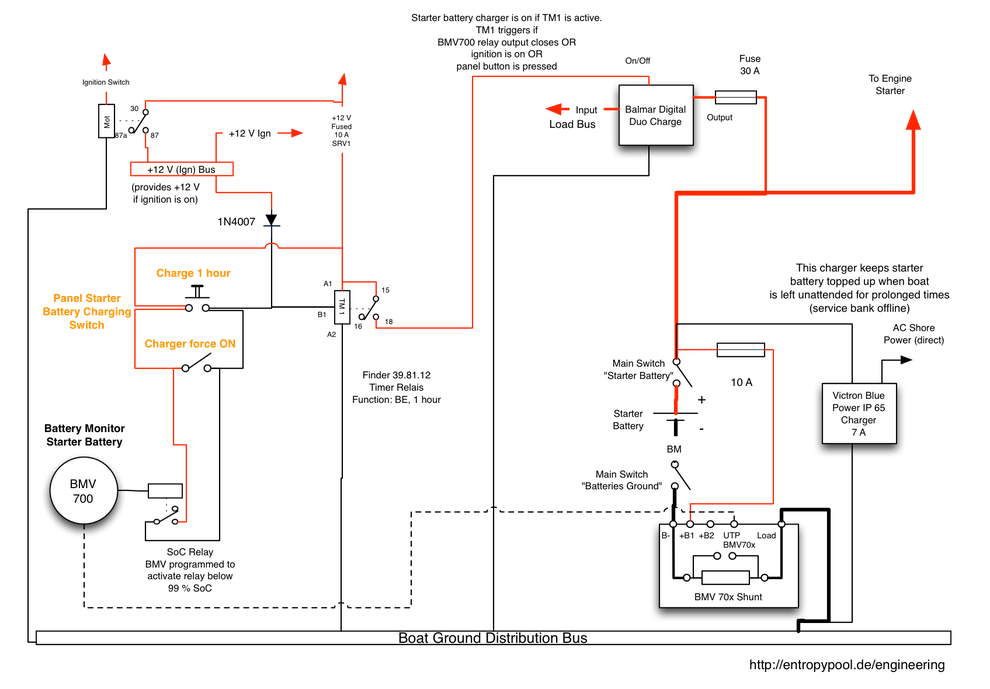
Finally we take a closer look on how the starter battery is charged - and when.
As described the starter battery is charged via a DC-DC Charger (Balmar Digital Duo Sterling Power Pro Charge B BBW 1212). I want the starter battery to be charged on the following conditions:
- whenever the engine ignition is on
- whenever the battery monitor device detects a battery voltage below 12.6 V
- whenever the battery monitor device computes the state of charge below 99 %
- whenever the operator wants the battery to be charged
In addition I want all charging to last at least one hour, regardless how short the triggering event occurs.
To do this, I added an additional timer relay, again a Finder 39.81.12 programmed to function BE and 1 hour. This function is a delayed off which can be retriggered. The relay gets permanent +12 V from the service bank. Whenever B1 of the relay sees +12 V, the relay closes 15-18 and thereby switches on the Digital Duo Charge BBW 1212.
A button press on the panel (or the panel switch in parallel to the button) will put +12 V on B1 of the relay, activating the charge cycle. If a permanent switch is used, the charger stays on as long as this switch is closed plus one hour.
In parallel to these manual switches we wire the BMV 700 relay output. The BMV 700 is programmed to monitor battery voltage and state of charge and activate the relay below 12.6 V and below 99 % SoC. It opens on 100 % SoC (which is determined by charging current tapering off by the BMV 700 device).
Finally we want the ignition to start charging as well. To do this, we connect a +12 V source which is active whenever the ignition is on to the relay. However, this must be done via a diode (a cheap 1N4007 or similar will do) in order to prevent current flowing back from the "button press" to anything on the ignition circuit side.
This setup makes sure that charging of the starter bank completely automatic but can still be manually forced.
It works - for us, that is!
You may imagine how relieved and happy I was to see that this design actually worked in real life. It even works extraordinarily well in my opinion.
Please note that this system design is designed to work for us. It will probably be too complicated for many other people, possibly including some yachting electricians.
When implementing such a system you should definitely be prepared to fix problems yourself. Do it only if you trust your own skills.
Write a comment
Jim Kevern (Thursday, 26 May 2016 21:17)
Correction. I also have a Balmar Duo Charge, and contrary to your perception it does NOT boost the DC voltage. It will cut the voltage down (like drop 14.8 down to 14.0, etc.) when required to adhere to which stage the charge of the start battery is, but it will not increase it.
But many thanks for documenting what you've done in such detail - great job and much help to me as I do my own.
Martin Bartosch (Thursday, 26 May 2016 22:05)
Thanks for this useful information, I was not aware of this. I'll have a close look on charging voltage next time I am on the boat and will possibly reconsider the Lead Acid Battery charging in the future.
garry crothers (Wednesday, 24 August 2016 12:19)
have you seen ths article where eric bretscher proposes keeping the SLA permanently connected to the charge bus through a diode splitter/isolator to ensure there will allways be a load attached. http://nordkyndesign.com/electrical-design-for-a-marine-lithium-battery-bank/.
It posses a problem getting the SLA fully charged, but it can be worked around, and does provide a higher level of safety.
Martin Bartosch (Wednesday, 24 August 2016 13:41)
Thanks for the link - I was not aware of this article. I totally agree with Eric on the fact that some charging sources must be protected from sudden disconnect of the load. This mainly affects devices which use electromagnetic generators of any sort to produce energy. In our particular installation this only applies to the alternator, the MPPT solar chargers can be safely switched off.
To protect the alternator in my installation I have designed the system as follows (this is also explained above):
The alternator B+ is connected after the main contactor but in front of the charge bus relay. This means that a HVC event (dropping the charge bus) will still leave B+ still connected to the LiFePO4 bank via the main contactor.
The alternator is shut down via a NO relay cutting power supply to the charge regulator, essentially shutting down the field current in the alternator. Voltage will sag in a controlled way when doing so.
This relies on the assumption that HVC happens before an isolation event. The HP BMS provides three outputs: HVC, LVC and Main Contactor. HVC and LVC are triggered on "warning levels", the Main Contactor is dropped on "protection level". Under normal circumstances there should be considerable time between HVC and dropping the Main Contactor. This assures safe disconnect of the alternator.
I am not a big fan of charging Lead Acid and LiFePO4 from the same charging source, not even via a splitting diode. In my design I have deliberately separated both batteries and do all normal charging from the load bus via a proper DC/DC step-up charger to the Lead Acid bank. IMO this is the only way to make sure that the starter battery is always properly charged.
Charging the starter battery directly with 13.4 - 13.8 V (typical terminal voltages during charging a LiFePO4 battery) will result in chronically undercharged Lead Acid battery and a very, very poor battery life.
A hybrid approach might be to use a charge splitting device in my design and still attach the DC/DC charger. This would provide a capacitive dump for a power surge after dropping HVC - but this will not happen in this design anyways, so why bother...
Martin Bartosch (Sunday, 28 August 2016 13:46)
Via the Contact form John asked me the following and referenced a discussion on Cruisers Forum (http://www.cruisersforum.com/forums/archive/index.php/t-140739.html)
"I note that you have chosen to cut the ignition power to the ALT, thus cutting field power to the Balmar alternator using the HVC. However, I believe the recommended approach is to cut power to the MC-614. Is there a reason you chose this approach?"
My answer:
When I designed this part of the system I only used the documentation of the MC614 for deciding how to shut down the field on the alternator. I was not aware of this CF discussion at that time.
Later I noticed these statements on CF but I decided not to modify my setup. It does work properly and so far I see no need to change it.
Some thoughts about HVC on the alternator with an MC 614:
Cutting +12 V (red) to the regulator:
Of course the safest approach, without power there will be no field excitation on the alternator.
Advantage: should work even if regulator fails. Most failsafe design.
Disadvantage: regulator is switched off in case of HVC. Sometimes this may not be desired. E. g. the tachometer output will not work (but no tachometer on HVC is not a big deal)
Cutting ignition (brown) input of the regulator:
Regulator stays online but stops providing field. Requires proper operation of the alternator regulator, there is a chance that in case of a malfunction of the regulator field still gets power, leading to overcharging the battery bank.
In this design this is possible but I consider this unlikely enough to live with it. IFF it happens, charging continues even after HVC.
The HP BMS will trip the Main Contactor when reaching cell protection levels. In this design this will stop charging hard by cutting B+ under full load. This will still protect the cells but likely damage the alternator diodes.
I am currently accepting this risk.
Advantage: regulator stays online and possibly keeps information about the current charge cycle.
Disadvantage: possibly prone to missed HVC on regulator damage. Possibly no soft ramp-up of field value once HVC condition goes away.
Cutting field wire directly:
This would be as safe as cutting the red +12 wire of the MC614. Regulator would still be running, but possibly ramp up field voltage (due to broken regulator loop).
Not recommended by me.
Advantage: none (well, alternator regulator stays online)
Disadvantage: no soft ramp-up, on the contrary a possible spike on field will happen when HVC goes away.
Wil Stevenson (Monday, 29 August 2016 21:13)
Beginning LFP student who will be installing a system on our Krogen 42 here, want to give you a most sincerely-felt 'Bravo, Bravo'. I've read CF and MaineSail's tome threads on LFP technology, both bring one from complete ignorance to the point where it feels achievable. Great stuff. BTW, despite best efforts, my marina friends scoff at the very idea, having the various airliner Li fires in mind. They will eventually see the light. Your analysis of the LFP approach with schematics (again, thank you for that!) is a very nice topping on the cake of an LFP learning curve.
The plan is to install an 800Ah, 32-cell 8P4S (fits in the existing battery box nicely, unlike 200Ah cells found so far) LFP bank, which will allow running for 3 days or more without recharge. Approx. half the weight and 2.5x the usable energy of the present Deka 8A4D 600Ah LA bank. The great little maraschino cherry on top will be a 300A DC generator which will recharge the bank in ~2hrs. A lot smaller, lighter, more efficient, and faster charging than the existing 8Kw AC generator, plus no under-loaded diesel engine issues. A paralleled second 2.5Kw pure sine-wave inverter will carry the AC loads.
The wheelhouse roof of a KK42 allows for several solar panels, and eventually quite a few walk-able panels (http://www.bruceschwab.com/solar-power/rugged-walk-solar-panels/) on the boat deck. Our dinghy will be on davits at the transom anyhow, only using the boat deck for long passages or high-theft area anchorages. There are some quiet and efficient wind generators out there now too (http://www.superwind.com/swe/index.htm). These will lengthen the time between DC generator bank chargings, hopefully eventually as long as once a week. The obvious plan is to rest quietly on the hook for extended periods of time when required.
The increasing efficiency, decreasing cost of solar panels and LFP cells, and evolving DIY technology make such a vastly-improved energy system affordable and doable for an average income person. Most exciting. If any, comments most welcome regarding the proposed system, and again, Thank You.
Martin Bartosch (Monday, 29 August 2016 21:31)
Hi Wil,
Thanks for the nice feedback, this is very appreciated! It's great to see that the effort to document our design is helpful for other cruisers as well.
Your planned setup sounds very sweet (but also a bit expensive - I know what I am talking about ;). Sounds a lot like you won't be having any energy shortage problems with all the charging sources. You can never have too many solar panels and your boat looks like it will be able to house a lot of them.
300 A DC charging from a generator is also amazing. Are you sure you will need a wind generator on top with all these charging sources?
In our setup the next thing we'd probably add is either a hydro generator (Watt and Sea, Save Marine or similar) or even a fuel cell (Hydromax or Efoy). We currently only have a shortage when cruising (moored we typically get away even or with a small energy surplus), so a hydro generator would make the most sense, but for now we think that running the engine for one hour a days is acceptable.
From our experience the most amazing capabilities of the LiFePO4 batteries is the ability to absorb every Joule of energy you throw at them. The solar panels' energy really gets absorbed and stored much better than on a Lead Acid system. This alone might be the defining difference to a traditional system.
Martin
Wil Stevenson (Monday, 29 August 2016 23:13)
Hi Martin,
I forgot to mention that your writing style is great too--you are talking about a fairly technical subject, but make it quite understandable. Cheers.
You're right, the proposed system is fairly expensive, in the $15k area all in. The largest initial expenses will be the LFP bank and DC generator. Being a fan of the extended temperature capabilities of Yttrium cells (so I understand) I want to go with Winstons. I do wonder a bit if a 32-cell bank is too many for balancing/maintenance issues.
The generator I like most for my system is the Polar Power PDC-8080VP-13 (http://www.polarpower.com/applications/marine/marine-products/marine-dc-generators/8080vp-13/), but having communication issues with them even in these early stages of planning, so might have to go another (and probably less expensive) direction. Been down that road before. Indeed a wind generator might be superfluous, but can be installed at a later date should the need arise.
Obviously we won't have a cruising power shortage ;-}. We moved away from sail to a trawler due to the want for more comfort/easier tasks as we have gotten older.
Regards,
Wil
Matt (Friday, 16 June 2017 21:39)
Hi,
First of all, great series of articles, thank you!
A question - I'm wondering why you have a separate HVC for each of the charging sources instead of one HVC just controlling the entire charge bus - that seems like it would be a lot simpler. When one trips due to too high voltage, wouldn't it trip ALL the HVCs anyway?
Martin Bartosch (Saturday, 24 June 2017 16:44)
Hi Matt,
Sorry for the late reply. It's all mentioned in the article, but to summarize: the Charge Bus has its own HVC to cut off all charging sources which can withstand sudden disconnect. The exceptions in my implementation are the alternator (charging is disabled by cutting field excitation in order to avoid blowing the diodes) and the Inverter/Charger. This device is both a load and a charging source, and I connected it to the Load Bus to avoid draining the battery in invert mode. Charging is disabled by a separate HVC relay on the AC input side of the device.
And the HVC relays are all operated by the BMS, not the other way round.
Cheers
Martin
Matt (Monday, 23 October 2017 17:16)
Thanks Martin for your response - makes perfect sense.
I've been reading up for the last couple of months on installing my cells safely, and this website has been a major source of information - the detail of the explanation and the clear wiring diagrams are a real boon to anyone trying to put in their own cells, so thank you!
Arden Wiebe (Thursday, 18 July 2019 18:27)
What were the different types of cell boards that Clean Power Auto produced. I have some that look different than what I have now. I plan on using one of the different looking ones to replace a failed cell board that does not trace.
All my other cell boards when traced between the spade connectors read 0.00 instantly. One cell board does not and the lowest it will trace to is 0.05v which sends a fault to the headboard.
Am I correct in this logic and can I take a chance on using one of these other different looking boards just to get the loop closed and the BMS back online?
Martin Bartosch (Thursday, 18 July 2019 20:53)
I am afraid I cannot really answer this question. Yes, we do use the House Power BMS and its cell modules, but I have not had a look at how they work. We luckily have a spare module in case one fails, but that's about it. I am also not inclined to do reverse engineering on it, if the BMS fails on Entropy I have a short term "Plan B" (replacing it from the portable battery bank), but this will immediately lead to a redesign phase where I will review the market and replace the BMS with a different type (e. g. a REC BMS).
Regarding your question, I recommend to post this question on the Cruisers Forum in the "Electrical: Batteries, Generators & Solar" section. Chances are not zero that someone on CF knows how to contact the original manufacturer or even has done the reverse engineering job already.
Jason P (Friday, 13 December 2019 01:42)
I am designing my system now and would like to do something similar to what you did with the shore power side of your inverter. I see that you put in an AC relay that opens both hot and neutral legs in the event of an HVC. Can you tell me what model relay you used here?
Also, I like your method for using your starting battery in which you have it charging from the LiFePO4 bank. Has this worked out as well as you had planned or would you do it differently?
Thank you
Martin Bartosch (Friday, 13 December 2019 12:09)
Jason, frankly I don't really remember which relay I used, but very probably it was a Finder FIN 4C.02.9 12V, FIN 48.52.7 12V or FIN 48.P5.7 12V...
And I still absolutely love the way the starter battery charging works via the DC/DC charger. It is totally independent of running the engine, and I totally love it that I can give the starter battery a 1 h recharge by flicking on the ignition switch for a second and turning it off immediately without running the engine. The timer relay will top up the starter battery then.
If I were to build the system today, I would not use the Sterling B2B (it's heavy and expensive), instead I'd now choose the smallest Victron "Orion-Tr Smart DC-DC Charger Isolated". Benefits: it's much smaller, highly programmable and most importantly isolated. The Sterling B2B connects ground between the batteries, and I don't like that very much.
Jason P (Friday, 13 December 2019 18:52)
Martin,
Thank you for the reply. I just realized that your inverter is 1600 watts and so the relays your suggested make sense. I have a 2800 watt and need 30A switching on the NC side which appears to be more difficult to find than I had expected. It looks like I am going to have to use an open style relay and put it inside a box to protect it.
I was actually thinking the very same thing with the DC to DC. The Sterling devices are great products but I think too much for this application. I was already looking at the Victron Orion-Tr.
Thank you again!
Martin Bartosch (Friday, 13 December 2019 21:34)
Hi Jason,
Well, 2800 W is quite something :)
Just a thought: are you sure you need the full 2.8 kW charging capacity from shore power? I understand you are living in 110 V country - a whopping 30 A on a shore power line sounds quite steep to me. Cables and connectors will have to be dimensioned to suit that. Having seen some interesting marina cabling already I have some doubts I would trust arbitrary marine installations to cope with this current. So one might consider limiting input current to the charger anyway to protect wiring and connections. And if doing so, you could go a step further and fuse the input side for this reduced current, e. g. 16 A. Thus current limited, it should be possible to find relays which switch 16 A.
On some charger/inverter devices (e. g. on the Victron Multiplus) you can artificially limit input power to a configurable current. In the case of Victron Multiplus, these devices have the capability of adjusting input power in the settings of the device.
BTW, the Victron devices provide something called power assist. This means you can still draw the full 2800 W from the inverter side, if the input is limited the system will draw additional required power from the battery.
Of course this only works if there are no continuous high loads, such as ACs.
Jason P (Tuesday, 17 December 2019 18:23)
Martin,
I appreciate your reply. The inverter does not charge at the full 2.8 kW. It is only capable of outputting 1.4 kW as a charging source. The 2.8 kW represents the amount of power it is capable of drawing from a shore power source (~24A). This allows it to both charge at full capacity as well as output an AC signal using the remainder.
Our system is already wired for 30A shore power, in fact it has 2 30A shore power connections which appears to be fairly common here. I am specifically looking for a 30A relay since the system already has a 30A input from shore power with 30A breakers and appropriately sized wire. I could go with a slightly smaller relay (25A) but I stand the potential to work it at its max current rating (unlikely but possible) so I would prefer the 30A.
I believe I have found a relay to meet my needs Tyco PRD-11DG0-12 however the 120V specifications for this relay are somewhat vague. It says it can support 30A @ 240V AC but for 120V AC it only says 1.5 Horse Power. This would suggest to me that it supports much lower than 30A for 120V AC since a 1.5 Horse Power motor will draw only ~half of this amount. I am trying to find out from the manufacturer what the current rating for 120V AC is. Hopefully it will prove to be what I need.
Again, thank you for your help and thoughts!