
2019-05-12 Update: Fixed typo in "logic table"
2019-04-05 Update: Fixed an error in the schematics: Q2, Q3 should be "B" type. The previous version had C and E swapped on Q2 (fixed in the version below).
2016-10-08 Update: Modified schematics to include additional MOSFET protection components (D3 - D6). Thanks to Eric (OceanSeaSpray) from nordkyndesign.com for pointing this out.
This post describes an electronic circuit which can be used to drive latching (bi-stable) relays from a controlling device which expects to drive a "normal" relay coil.
The circuit presented here is designed to connect directly to a House Power BMS, replacing either HVC or LVC relay with a latching relay, but the circuit should also easily be usable in other application in which latching relays need to be driven from a controller providing constant output levels.
The House Power BMS used in Entropy's design only provides outputs for "traditional" relays. The main contactor output as well as High Voltage Cutoff and Low Voltage Cutoff outputs are all level driven. The BMS pulls the output to ground in order to activate the attached relay.
For the main contactor, the BMS output "E" is typically always active (pulled to ground) in normal operation mode, however outputs "B" and "C" (LVC and HVC) are pulled to ground in case such an event is detected.
Entropy's battery management design requires three relays to be active in normal operating conditions (main contactor, load bus contactor and charge bus relay), all of the are contributing to the idle consumption of roughly 1.5 - 2.0 A.
It is possible to reduce the residual current flowing through the relay coils by about 50 % because the holding voltage of a relay is only about 50 % of the nominal voltage. There are "coil optimizers" which do exactly this, for example the Tyco EV200, resulting in a holding current of only about 170 mA for a 500 A contactor. Not bad.
However, our charge bus relay does not have a coil optimizer. It draws about 340 mA, 24/7, a whopping 8 Ah per day!
Edge Detector driver for latching relays
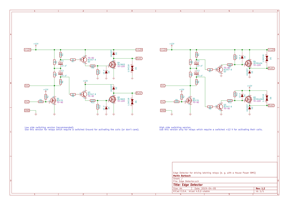
The schematics below show two variants of an Edge Detector circuit for driving latching relays from a constant level controlling device.
The variant on the left hand side is designed is the "low side switching" version, it is electrically preferred and N Channel MOSFETs are more common than P Channels which are need for the "high side switching" version on the right hand side.
There are some latching relays, though, which require switching the high side, for example some BlueSea relays.
Note: I have only tested and verified the low side switching version!
Installation:
- connect +12V and GND. +12 V should ideally always be connected (even if HP BMS is switched off - this way this circuit can manage the relay coils)
- connect Out1 to "On" coil of latching relay
- connect Out2 to "Off" coil of latching relay
- the common side of the relay coils shall be connected to +12 V (Low side switching version: output connects to GND) or GND (High side switching version: output connects to +12 V)
- connect HP BMS outputs:
- connect E (main contactor) output to In2
- connect B or C (LVC, HVC) output to In1
- if no main contactor function is required (pure emulation of the LVC/HVC relay) connect In2 to ground (or completely remove R1, R2 and Q1 from the circuit if In2 is not needed)
- it is allowed to join B and C outputs of the BMS and connect to In1 to achieve "open relay on LVC or HVC"
Idle current draw is less than 6 mA. This can be reduced by optimizing the circuit: replace R3 and R4 with a higher value, e. g. 4.7 kOhm. The circuit will continue to work, but it will require more time to "get ready" before the next edge can be detected.
Basic operation
Switch +12 V on with In1 and In2 open: relay turns off if it was on.
| In2 | In1 | latching relay state |
| open or +12V | any | off |
| connected to ground | open or +12V | on |
| connected to ground | connected to ground | off |
Timing/Logic Diagram
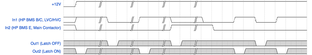
This timing diagram might help to understand operation of the design.
With no +12 V power supply connected the outputs Out1 and Out2 are - of course - disconnected/floating (grey).
Marker "a":
+12 V is applied. In2 (BMS E) is pulled to ground (i. e. the BMS activates the main contactor). In1 is open (i. e. the BMS does not signal a LVC/HVC)
Out2 is pulled to ground for about 1/10th of a second, switching ON the latching relay.
Marker "b":
An LVC/HVC event happens: In1 is pulled to ground.
Out1 is pulled to ground for about 1/10th of a second, switching OFF the latching relay.
Marker "c":
LVC/HVC condition disappears: In1 returns to open.
Out2 is pulled to ground for about 1/10th of a second, switching ON the latching relay.
Marker "d":
The main contactor is dropped by the BMS: In2 is open. The state of In1 is irrelevant.
Out1 is pulled to ground for about 1/10th of a second, switching OFF the latching relay.
Marker "e":
The main contactor is activated again: In2 is pulled to ground by the BMS. However, In1 is still pulled to ground (LVC/HVC still persists).
Nothing happens.
Marker "f", "g", "h":
Normal operation with main contactor activated, but LVC/HVC condition appears/disappears.
Out1/Out2 is triggered accordingly (see above "b", "c")
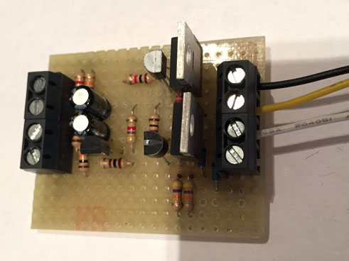
See it in action
Note: this early prototype does not feature the In2 input, it only demonstrates operation based on In1.
Write a comment
Jay on S/V Priority (Sunday, 22 March 2020 10:01)
Martin, Thanks for sharing your LiFePO4 battery system design. It has been extremely helpful.
I found a couple errors in this latching relay driver circuit that may benefit others trying to build this circuit. The IN1 connection should be between R3 and R4. In addition, if Q1 is not used, the R4 and R6 must be connected to GND. You stated Q1, R1 and R2 could be eliminated but I didn't get that a GND was needed. Also on the High Side version the S and D markings on Q4 and Q5 are reversed.
Again, thanks for sharing. I am designing a LiFePO4 battery upgrade for our Cape Dory 33. Your design details and explanation have been very helpful
Martin Bartosch (Sunday, 22 March 2020 14:41)
Thanks for your comment, Jay, very good to hear that these blog poses were useful for you. I will review the details in your comment later when I find the time...
Cheers
Martin
Sergei (Thursday, 11 June 2020 10:36)
Hi Martin,
We are still in Morocco as the lockdown now extended until July 10th.I had a question regarding your latching relay driver, would it work for 24V BlueSea latching relay ML-RBS?https://www.bluesea.com/products/7702/ML-RBS_Remote_Battery_Switch_with_Manual_Control_-_24V_DC_500A
I am moving slowly forward with LifePo4 Winston design and I decided to get 8 Winston 700 Ah cells for 8s config and REC BMS SI for my BMS.
I hope you are well with you and the family!
best, Sergei
Martin Bartosch (Wednesday, 17 June 2020 08:03)
Apologies for the late reply, Sergei. If you look at the schematics for the BlueSea latching relay it seems to indicate that the relay expects to be operated with a common ground and a positive voltage applied to the coils.
If this is required, you will have to implement the "high side switching" circuit described above. Please note that I have not tested that circuit variant personally, and it may very well not work properly.
I am not sure if this is really required, as relays typically do not care about polarity. Maybe there is some circuitry inside which demands it, but it's unlikely in my opinion. So it MIGHT be possible to switch the relay coils also with a common + and momentarily applying ground to the coils. If this is the case, the low side switching variant would work, and for this I know that the schematics actually work.
Cheers, Martin
Kamal (Wednesday, 29 July 2020 15:13)
Thank you for the schematics
I want to use that for 24v dual coil latching relays, common +, what changes should I make to the above schematics
Martin Bartosch (Wednesday, 29 July 2020 15:25)
Kamal, I would double the values of R3, R4, R5, R6. D3 and D4 should be 30 V each. The rest should pretty much stay the same.
Cheers, Martin